Cutting polylines
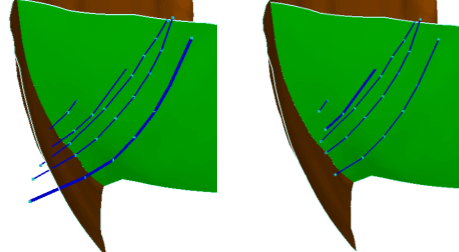
Polyline cut: Input polyline set and resulting polyline set click to enlarge
Use the Cutting tool in the Structure Builder to cut polylines at tri-mesh intersections based on a specified gap size, dip, and smoothness level.
Other means of handling polyline-tri-mesh intersections are available in the Structure Builder group.
- Select a surface set or seismic interpretation.
- Click Calculate. This will populate the table on the form with all the polyline sets and tri-meshes that are intersecting.
- Select the polyline set -tri-mesh intersection you want to modify. You can click the individual check boxes or right-click the list and make a selection from the context menu.
-
Specify the cutting settings or accept the ones listed in this step. You can change, select or deselect the following values:
Gap size Define the size of the gap that is created.
Dip When you specify a dip value, only nodes with a dip property value larger than this will be removed.
Smoothness When you specify a smoothness value, only nodes with a smoothness property larger than this will be removed.
Re-triangulate modified polyline sets Automatically re-triangulate the tri-meshes that are adjusted by the cutting process (recommended).
Recalculate intersections Automatically recalculate the polyline-tri-mesh intersections after the cutting process (recommended).
- Click OK or Apply to perform the cutting process.